

Thin film simulation (reflection, transmission, ARC, colour)
Products > Experimental and theorectical investigations of optical coatings
The reflection (R) and transmission (T) and ellipsometric parameter cos(∆) and tg(Ψ) for thin films on substrate, like Mask blanks, were determined with the help of the thin-film optics of Havens [1]. All calculations for R, T, cos(∆) and tg(Ψ) take into account the inhomogeneities and the roughness of the layer. For the consideration of film inhomogeneity is used a convolution of reflection and transmittance spectrum with a Gaussian function. The film roughness is considered in the Fresnel formulas, which were derived from the Helmholtz-Kirchhoff scalar diffraction theory according to Beckmann, Spizzichino [2] and Ohlidal [3].
[1] O. S. Havens, The Optical Properties of Thin Solid Films, London: Butterworth (1955)
[2] P. Beckmann, A. Spizzichino, The Scattering of Electromagnetic Waves From Rough Surfaces, Pergamon Press, London, 1963
[3] I. Ohlidal, K. Navratil, F. Lukes, J. Opt. Soc . Am. 61 (1971), 1630-9
The simulations allow to consider the multiple incoherent reflections and transmittance within the substrate, example for the glass back reflection.
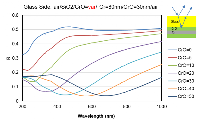
Example for Cr / CrO:

Example for Titan:
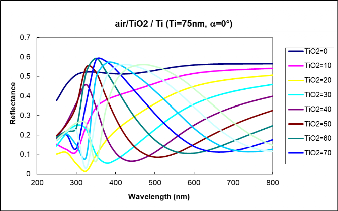
Fig. 3.4. An example for the anti-reflection coating of Ti with TiO2.
Calculation of optical density
In addition to the requirements for reflection and anti-reflection, there are also requirements for transmission and optical density. This is possible by adjusting the thickness of the coatings on glass or quartz glass. The following figures show some dependencies.
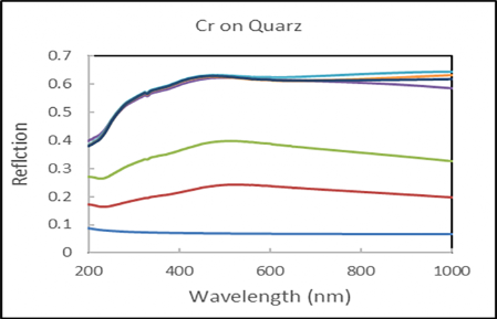
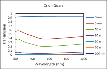
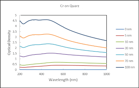
Fig 5.1. Reflection , transmission and optical density of chromium coated quartz
Simulation of Coloring
Special coatings are applied for chromatic effects or anti-reflective coatings for reflections as visual effect for the eye. The CIE's XYZ color were calculated by integrations
X(red)=k ò R(l) x(l) si(l) dl,
Y(green)= k ò R(l) y(l) si(l) dl,
Z(blue)= k ò R(l) z(l) si(l) dl,
where R(l)-reflection, si(l)- spectral standard of illumination (i=A, C, D65) and x(l), y(l) and z(l) are the color matching functions based on physiologically perceived colors in human color vision.
Examples are shown in Fig. 4.1-4.5.
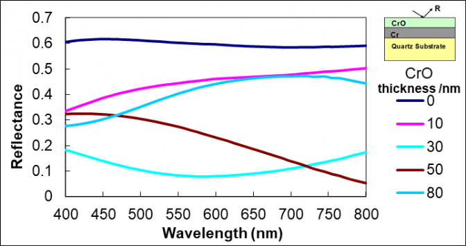
Fig. 4.1. Simulated Reflection R(l) for the coloring calculations shown in Fig. 4.2.
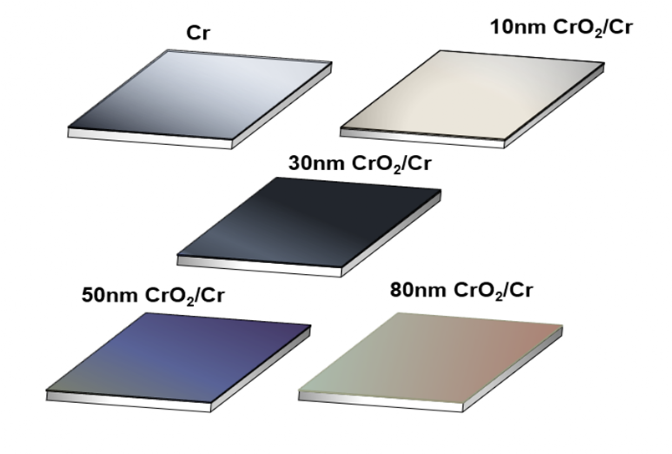
Fig. 4.2. Coloring effect of CrO coated Cr.
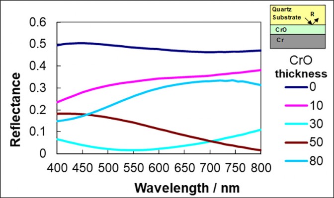
Fig. 4.3. Simulated Reflection for the coloring calculations shown in Fig. 4.4.
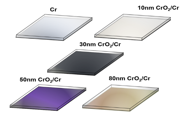
Fig. 4.4. Colour effect of CrO and Cr coated glass substrate viewed from the glass side.
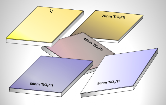
Fig. 4.5. Colour effect of TiO2 and Ti coated glass substrate.